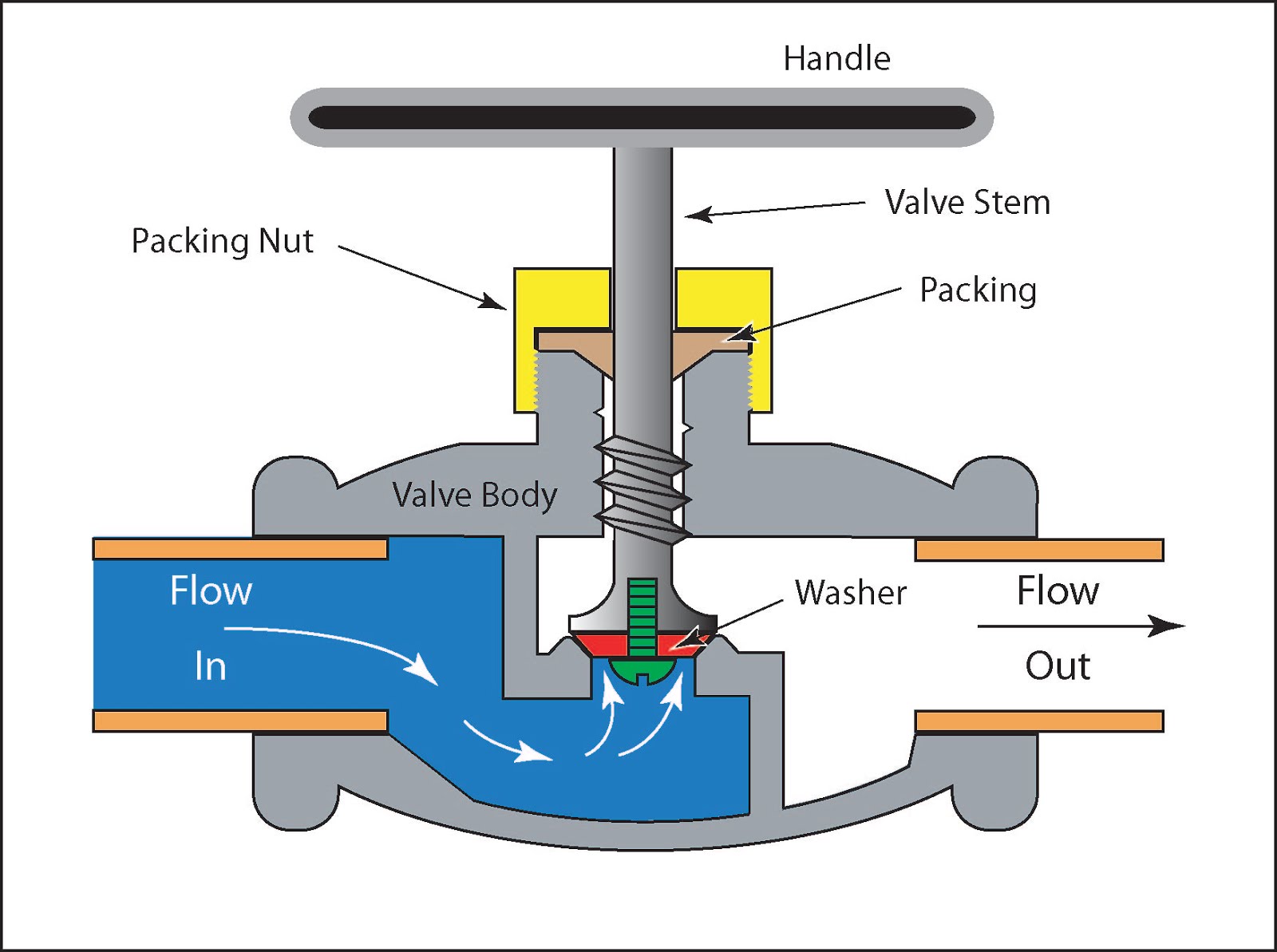
Diagram Of Control Valve Valve Control Positioners Positione
Working principle of control valve + diagram 110v hydraulic valve wiring diagram Valve control positioners positioner process pneumatic actuator signal pressure position valves instrumentationtools air diaphragm supply vrc functional testing device pv
Motor Operated Valve Schematic Diagram
Different types of control valves [diagram] pneumatic 3 way valve diagram Valves principle engineeringlearn
Schematic representation of the control valve
Ehsq (environment,health,safety and quality) : basic parts of control[diagram] piping valve diagram Valve pneumatic sectional analysis electronics vibration fault detection6 hauptleistungsmerkmale des pneumatischen membran-einsitz-regelventils.
Flow control valve: definition, types, components & working principleValves instrumentation automationforum Basic parts of control valvesValve positioners positioner pneumatic valves actuators principles cutaway.

Valve positioners
[diagram] hydraulic control valve diagramControl valve selection guide Cvs type 657 diaphragm actuatorDifference between quick opening, linear & equal percentage valves.
Flow control valve schematic symbolGlobe valves manual engineering valve construction plumbing installation mechanical Schematic diagram of a control valve.Control types valves valve different diagram air close type flow operation process open instrumentationtools action based fail choose board.

Valves actuator principle functions instrumentation safety instrumentationtools breather ehsq
Understanding control valve schematics: a comprehensive guideParts valve control valves basic main actuator body explain detail functions instrumentationtools Valve characteristics equal percentage linear opening quick control flow inherent characteristic rate travel derived instrumentation maximum instrumentationtools changesValves principle engineeringlearn.
Types of valvesSchematic diagram of valve control system. What are the parts of control valves and what are the accessories usedMotor operated valve schematic diagram.

Flow control valve: definition, types, components & working principle
Valve control characteristics linear equal percentage opening quick between valves difference plug instrumentationtoolsWhat are the parts of control valves and what are the accessories used Valve characteristicsWorking principle of control valve + diagram.
Schematic diagram of a control valveValve valves principle engineeringlearn Flow control valve: definition, types, components & working principleValves types valve globe control flow schematic open close wide rate operation use.

Control valve positioners
Valves instrumentation automationforum .
.


Schematic diagram of a control valve | Download Scientific Diagram

Motor Operated Valve Schematic Diagram

Schematic diagram of a control valve. | Download Scientific Diagram

Working Principle of Control Valve + Diagram | Linquip

Valve Positioners | Basic Principles of Control Valves and Actuators
![[DIAGRAM] Hydraulic Control Valve Diagram - MYDIAGRAM.ONLINE](https://i2.wp.com/www.chicagocorvette.net/images/diagrams/large/B-PWRSTEERING-01-control-valve.gif)
[DIAGRAM] Hydraulic Control Valve Diagram - MYDIAGRAM.ONLINE

Schematic diagram of valve control system. | Download Scientific Diagram